
AXBB Wiring to driver question
3 posts
• Page 1 of 1
AXBB Wiring to driver question
![]() by Fabmonster » Sun Sep 22, 2019 1:04 am
by Fabmonster » Sun Sep 22, 2019 1:04 am
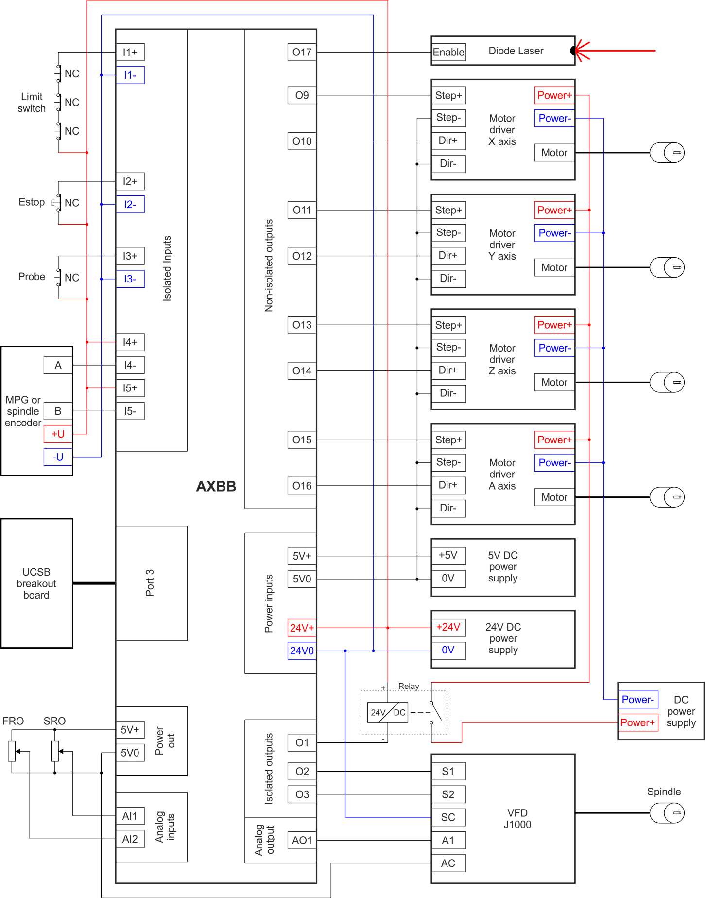
Here is my driver please explain to me how to wire this thing. I’ve been trying to figure it out for a week with no success. I tried wiring cp- cow- to ground 5vo on axbb then cp+ to pin 9 port 1 and cw+ to pin 10 port 1 and no movement. HELP -PLEASE
- Attachments
-
- Fabmonster
- Posts: 10
- Joined: Tue Sep 17, 2019 3:29 am
- Location: San Antonio, Texas
Re: AXBB Wiring to driver question
![]() by Robertspark » Sun Sep 22, 2019 6:32 am
by Robertspark » Sun Sep 22, 2019 6:32 am
CP is your step signal
CW is your direction signal
section 9.2 of the manual shows 2 wiring options
https://www.google.com/url?sa=t&source= ... M24AixmJtf
if it were me:
I would wire the 5V0 to CP- and CW-
I would then wire one of the non isolated outputs OF to 017 to CP+ and a separate (different) non isolated output to CW+
but as section 9.2 shows you you could wire up CP+ and CW+ to 5V+ and then you would wire up CP- and CW- to separate non isolated outputs OP9-17
either will work
it is clearly shown in this diag
https://www.cncdrive.com/img/AXBB-E_5.png
UCCNC Macro Manual v1.2113 - https://drive.google.com/drive/folders/ ... sp=sharing
- Robertspark
- Posts: 1892
- Joined: Sat Sep 03, 2016 4:27 pm
Re: AXBB Wiring to driver question
![]() by cncdrive » Sun Sep 22, 2019 7:17 am
by cncdrive » Sun Sep 22, 2019 7:17 am
If the CP+ is wired to a non-isolated output and CP- is wired to 5V0
Or
if the CP+ is wired to the +5V and the CP- is wired to a non-isolated output
then it should run to one direction even if the CW+ and CW- is left unconnected.
Or
if the CP+ is wired to the +5V and the CP- is wired to a non-isolated output
then it should run to one direction even if the CW+ and CW- is left unconnected.
- cncdrive
- Site Admin
- Posts: 4715
- Joined: Tue Aug 12, 2014 11:17 pm
3 posts
• Page 1 of 1
Who is online
Users browsing this forum: No registered users and 4 guests